Friday, May 20, 2016

Drum on Public Display


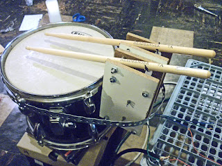
A fun uniting of digital (Arduino) and analog (human) output. Kitchen pots were placed upside-down to the right of the drum. An extra pair of drumsticks were marked as "Human Input "A" and "Human Input "B". A user-controlled potentiometer supplied analog voltage readings to the Arduino, which were then judged by IF statements in the code. The resulting data determined which of three drum rhythms to play (with a 4th IF statement for "off"). Each drum rhythm was just a series of 1's and 0's in an array. After the strikes, I would recommend a delay of about 20 miliseconds. Also, play with a delay at the end of the rhythm loop (depending on desired tempo.)


// A little example code for one rhythm
// "val" is the pot reading. My code has this value remapped from 0-4000.

val = analogRead(pot);                        // read the pot to determine current value
val = map(val, 0, 1023, 0, 4000);    // you do not have to remap like I did,
                                                             // but if not, adjust code accordingly

//Note: when val<500, I have it sit in a WHILE statement until the value breaches
//          that threshold. This is a static "off" position.
                                                         
//////////////////////////////
//////////////////////////////
/// POT IS SET FOR BEAT 1
//////////////////////////////
//////////////////////////////
if (val>500 && val<=2400){               // potentiometer reading in this range???
 
  tempo=120;    // this is just a delay value, not tempo in the traditional sense
 
for (int i=0; i < 64; i++){                     // 64 values in my rhythm array
  if (drum1[i]==1){                              // drum1 (stick 1) array value == 1, hit the stick
    digitalWrite(drum1Pin, LOW);       // NOTE: LOW for my setup. Yours may be different.
                  }
  if (drum2[i]==1){                              // drum2 (stick 2) array value == 1, hit the stick
    digitalWrite(drum2Pin, LOW);
  }

    delay(20);
    digitalWrite(drum1Pin, HIGH);      // reset pins for next hit
    digitalWrite(drum2Pin, HIGH);
    delay(tempo); 

val = analogRead(pot);                        // after any strikes, read pot again for next action
val = map(val, 167, 1023, 0, 4000);
                                                         

  if (val<=500 || val>2400){                // IF POT OUT OF RANGE,  BREAK LOOP
                                                            // (resume main loop)
    break;
                          }
  }
}
Tuesday, May 17, 2016

Testing the Drum

After a little Arduino coding, I have both drumsticks drumming at the same time (success)! This is after:

- Burned up an actuator
- Sent 2 more actuators to electronic heaven

Ultimately, I will add new Arduino code which alters the beat and which drum stick hits. Other than "beautifying" it, this project is complete! I'll just add a few kitchen pans and extra drumsticks which an observer can walk up to and start jamming with the electronic drummer! Analog meet Digital! Oh, I forgot to mention the use of a potentiometer to change to different drum beats. When I have time, I'll get that coded. This bare-bones rhythm is just for testing that both sticks work. I'll be coding some better ones.


Power Supply

I found a Dell D220P 12V 18A power supply second hand for $5.00! In order to "wake" this thing up from hibernation mode, you need to wire it differently. Really not difficult. Just gathering wires and connecting them together. Here is a link to more info to help with the wiring:

http://helifreak.com/showthread.php?t=188279

Attaching to Drum

The whole thing gets attached to the drum by use of a 3/4" steel strap (commonly used for hanging pipes.)


Connecting the Drumsticks

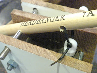
I drilled 1/4" holes through the drumsticks. One accepts a bolt while the other gets zip-tied to the actuator (this one needs to be tightened further).


Motors are in the assembly

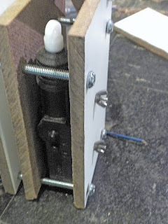
Motor placed in the assembly. 5" bolts were used to secure the pair of motor holders.


Wood for motor housing

Using wood of approximately 1/4" thickness.


Relay Module

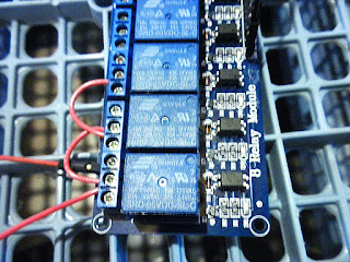
Here is my relay module with 8 possible connections. From what I hear, Arduino can only power up to 4 of them at a time. Can anyone confirm?


Monday, May 16, 2016

Crispy Actuator

Okay, so I learned that car door lock actuators hate to have constant power applied to them for too long (accidentally)! Ahhh.....the sweet smell of burning plastic.... Anyone bring marshmallows? (sigh)

Using a relay module to control the actuators. What I believed was setting the pin to LOW actually read as HIGH on the relay (on the N.O. side). Hmmm..  More actuators.

Sketching out the idea

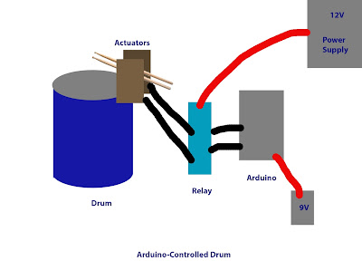
My very rough sketch for this project.


Arduino-Controlled Drum

Yet another project that I want to bring to life. An Arduino-controlled drum! I have been inspired by various online posts and wanted to give it a try.

A colleague loaned me an old tom-drum. I plan to outfit this with drumsticks pivoted with door lock actuators (the ones they use for cars). A slightly higher-current DC power supply will be necessary being these little guys are fairly power hungry (something like 3.5A each).

I will program the Arduino with various drum beats which will be user-selectable via a potentiometer.

How about some good old analog user interaction added in? Nearby, I will place found items such as pots/pans to be used as "instruments" with a separate set of drumsticks for the viewer to jam along with the electronic drum.

Okay, this is my initial plan. Let's see how it pans out! (did I just say that?)


Tuesday, April 12, 2016

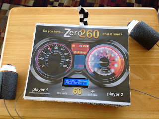
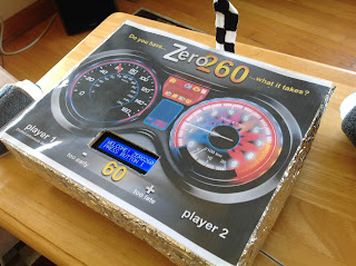
And here is the project in its final form! Notice the checkered flag? It's hooked to a servo and leans to indicate who wins each round. If my video camera were working, I'd add video. Hopefully soon! I know you're dying to see how it actually functions!


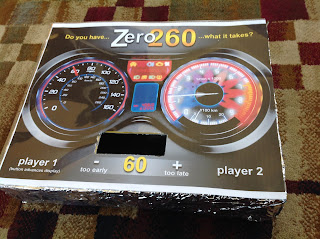
Box lid design. Looking more finalized.


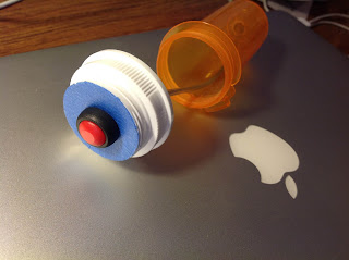
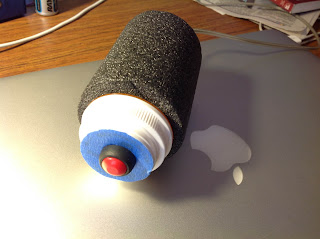
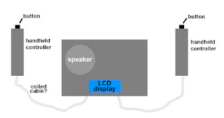
What do I have on hand to make the hand-held buttons? Walgreens pill bottles should work! But they're kind of ugly.


How about if I wrap them in pipe insulation! Perfecto!


Doesn't this wiring look better? I custom cut new wires after everything seemed to be going well. A speaker gets added to the wiring (not shown). Speaker to beep for counting purposes and special in-game sounds.


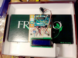
Hey,...sweet idea! Mount it all on top of a Frango Mints box!


Even sweeter idea??? Mount all of that inside a chocolate box!


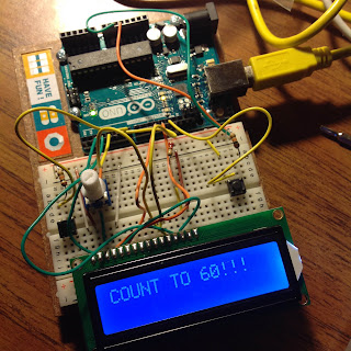
Hey, the LCD actually is working! I must have done something right.


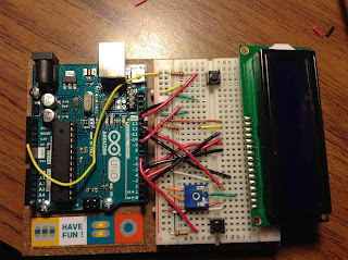
My rough wiring is in place.


The LCD wiring is a little confusing if you don't look closely. See how 1-GND is on the left in text, but the pin is actually on the far right?


Testing some push-button wiring. The process begins!


Beginnings of an idea

My goal is to create an interactive electronic game where two people are able to play head-to-head. I will create hand-held buttons for player input and will also implement use of an LCD screen to give users feedback as to their progress in the game.  I anticipate the coding will be the trickiest part of this project. I'll keep you posted!

Game:

Game will beep 10 times at an interval to be determined by a random number. (between 250-1000ms). RandomSeed will be introduced to create an even better random interval.

After 10 beeps, players continue counting next 60 intervals in their heads (game goes silent). When a player believe the next 60 intervals have passed, they hit their button. After both players have hit their button, results are calculated.

Time (in seconds, with 2 decimal places) is displayed on the LCD. Player closest wins the round. Play continues for 5 rounds, or until a player reaches a score of 3. Player with 3 is declared the winner!